CVTIA System Pipe and Flow Data
Data Items for the CVTIA Irrigation System (Last updated 9/28/20 by Hank LuBean)
Pipe size and pipe length from head gate:
From canal to Headgate approx. 16’ of 4” pipe; from Headgate 1650’, 5” PVC across golf course, under Baker in plastic conduit, to 85’ West of centerline of Ashland along south side of 17th; then 180’, 4” PVC to Aurora laterals; then 135’, 3” PVC from Aurora laterals to Aurora/Anne laterals; then 250’, 3” PVC from Aurora/Anne laterals to Anne/Sunset laterals along the North side of 17th; then 135’, 2” or 2.5” PVC from the Anne/Sunset laterals along the North side of 17th to the drainage culvert on the East side of Sunset Highway by the stop sign.
[Note: the historical file diagrams currently available indicate 2.5” PVC from Aurora/Anne laterals to Anne/Sunset laterals but due to repair of the main line in 2014 (Hank dug into it while putting in his geothermal system) and he put in a 3” repair collar 15’ East of Anne or about 10’ East of the new main valve installed in 200x on the East side of Anne. It needs to be verified whether there is 3” or 2.5” main line PVC East of the Anne/Sunset laterals up to shut-off valve on the East side of Anne. Also, the original Aurora lateral were to be 2.5” to start (when the lateral path was above the East side of the Aurora lots vs. along Aurora Ave.) but the other laterals down stream of Aurora are 3” to start with. The 2.5” value for Aurora laterals needs to be verified when it is dug up in the future to repair or replace valves or repair lines.]
Distance (pipe length) from head gate to:
Ashland – 1570 ft; Aurora – 1825 ft; between Aurora & Anne – 1960 ft;
between Anne & Sunset – 2213 ft; Sunset Hwy – 2347 ft
Vertical distance (Static Head) from head gate to:
Ashland – 82 ft; Aurora laterals – 114 ft; Aurora/Anne laterals – 131 ft; Anne/Sunset laterals – 157 ft;
Static Water Pressure at no flow conditions (based on Head / 2.31) from head gate to:
Ashland – 35.5 psi; Aurora laterals – 49.4 psi; Aurora/Anne laterals – 56.7 psi; Anne/Sunset laterals – 68 psi;
Water Pressure at 100 gpm flow conditions (based Hazen-Williams pipe losses) from head gate to:
Ashland – 34.1 psi;
Aurora laterals – 47.5 psi;
Aurora/Anne laterals – 53.4 psi;
Anne/Sunset laterals – 62.1 psi;
Pipe Flow Theoretical Capacity: in gpm (Hazen-Williams Formula, pipe limit – not orifice):
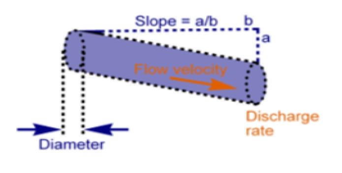
hf = 0.002083*L*(100/C)1.85 * (gpm1.85 /d4.8655)
hf/L = a/b = .002083*(100/C)1.85 * (gpm1.85 /d4.8655)
d = Pipe Dia. in inches, gpm = gal/min
C = Roughness coef. = 150 for pvc
Pipe flow maximum gravity flow capacity or capability from canal and head gate to/at:
Canal to Headgate (4” x 16’, 18” head) – 420 gpm;
Ashland (5”) – 591 gpm; Aurora (4”) – 362 gpm;
between Aurora & Anne (3”) – 163 gpm;
between Anne & Sunset (3”) – 153 gpm;
Orifice Flow Rate at Head Gate based on submerged orifice formula: (Orifice limit)
Q = .61 * A * (64.4[H-h]).5,
where Q = flow in cfs, A = orifice area in ft2,
Height Change (H – h)
= head diff before and after orifice in ft.
(conversion: gpm = cfs x 448.83, in2 = ft2 x 144)
Current CVTIA Orifice limit:
CVTIA Orifice Area – A, is 6.62 in2, 2” x 3.31” (at 14.07 shares x 5.5 gpm per share):
Q = 0 gpm and A = 6.62 in2 for H-h = 0 in]
Q = 41 gpm and A = 6.62 in2 for H-h = 2 in
Q = 77 gpm and A = 6.62 in2 for H-h = 7 in (WRD uses 5 inches level above orifice as a rule of thumb)
Q = 117 gpm and A = 6.62 in2 for H-h = 16 in
Q = 143 gpm and A = 6.62 in2 for H-h = 24 in
(The physical limit of head (H-h) in our 60” head gate box is about 36”. At zero flow the water level is the same as the canal and is down about 12” from the top leaving 48” of water in the chamber. The chamber outlet is right at the bottom and is 5” so that leaves 43” of water above the outlet. Air starts to be sucked into the outlet when the water level gets to about 6” to 7” above to outlet; that leaves about 36” of head to be utilized before significant air sucking. The formula doesn’t hold, or is not as accurate when the head gets more than 24” since, at more than 24”, the orifice is no longer submerged and the orifice flow would be a bit more than what is calculated because the flow from the orifice would not be as restricted as it is when submerged. The head gate outlet sits at the bottom of the head gate box and starts to suck air at somewhere around H-h of about 38” or so at which point head losses greatly increase and consequently the pressure downstream drops off considerably.)